14. Characteristics of glazing materials
14.1 Historical review
Up until the end of the nineteenth century and start of the twentieth, natural light was the primary source of lighting for buildings. The window in a wall or roof was the only way for natural light to penetrate the space. For as long as broad use of glass was not yet used for windows, there was no possibility of physically separating outside from inside. The open window let winds, dust, pollution, heat, cold and noise in. The options were full exposure of the opening to allow daylight in, or closing the aperture with materials that blocked the light. The only light penetrative materials used before glass were fine panels of schist or mica found in very few quarries. Other options were fabric or paper dipped in oil. The problem was that they offered only limited thermal protection, blocked most of the daylight, and prevented anyone inside from looking out. Nor did it affect the climate indoors, which remained almost identical to that of the outdoors. To stay warm, people need to add on layers of clothing, or use heating, since it was virtually impossible to ensure a controlled internal climate [12.1.1].
Glass was invented thousands of years ago. It was used for many purposes, such as jewelry, ornamentation, utensils and more, but never for glazing. Lacking was the knowledge for making a flat, thin, transparent yet sufficiently resilient panel of glass.
The first method for manufacturing glass intended for glazing involved spinning a lump of soft molten glass at the end of a rod. Spinning led to changes in the lump’s shape as a result of centrifugal force. This made it possible to form round glass panels, which were then fitted into appropriate openings. The process was primitive, expensive, and time consuming. Shapes other than circles required cutting, causing substantial loss of the originally produced round panel.
Broader use of glass for windows began in Europe in the twelfth century. Glass, being very expensive, was installed primarily in prestigious buildings such as palaces and houses of prayer. The French and Germans developed methods for using colored glass, which was employed to advantage in stained glass (vitrage) panels in churches and cathedrals. The result was impressive: when natural light shone through the windows, they showed images of astonishing forms and colors. Even today we are amazed by the richness of these colorful stained glass windows. An excellent example are the modern works of glass art by Marc Chagall at the Hadassah Ein Karem Medical Center in Jerusalem, and the vitrage by Mordecai Ardon in the lobby of the National Library at Hebrew University in Jerusalem’s Givat Ram campus.
During the sixteenth to eighteenth centuries, methods were developed to pour glass panels of ever increasing sizes. However, the pouring method was imprecise. Once poured, both sides of the panel needed polishing to straighten the planes and make them parallel so that light could penetrate without distortion or causing the view seen from the window to appear ‘wavy’. Glass was still very expensive, and was installed only in prestigious buildings or homes of the wealthy.
The expanded use of glass during that period began to be seen as a status symbol, which was not missed by the tax hunters, ever hungry for expanding their incomes. In European countries such as England, Holland and others, a levy was placed on windows. Interestingly, the taxation methods impacted the production of glass and therefore the development of architecture in those countries. In 1697, for example, England taxed glass according to the number of windows in a building, possibly to make calculating the tax easier. But this motivated the production of extremely large windows, making it possible to plan a building with greater window space but a smaller number of windows. During that same period in Holland, taxes were levied on the entire facade of the building facing the street. This caused builders to plan narrow fronted buildings with greater depth, so familiar to us today. Getting light into the building meant increasing the glazed area on the front. To this day, Dutch architecture is typified by large front windows, even if at the expense of privacy.
The Industrial Revolution hastened the development of more advanced methods for bringing daylight into buildings. At the end of the nineteenth century, glass was being manufactured in thin, relatively large panels, using an extremely high smelting oven. The molten glass flowed vertically downwards due to the force of gravity. In the process of its slow cooling, the glass would be transferred through a system of rollers, producing glass panes of reasonable optic traits. However, due to imperfect parallelism of both sides of the panel, distortions still caused the viewer to see wavy landscapes, or window shoppers to see wavy products on display. Reaching a higher optic level still required polishing of both sides to smooth, parallel planes. But polishing pushed the price of glass up even more. Polished glass was installed, therefore, only in prestigious buildings or in display windows of commercial stores.
The Industrial Revolution was leading to new technologies in building, including the use of cast iron. The combination of iron frameworks and large areas of glass made it possible to develop the structure now known as glass houses. One of the most famous was the Crystal Palace Exhibition Hall of London. These structures were also used to huge advantage by agriculture as greenhouses, and especially in roofed public and shopping centers. The roofed glassed area of a building came to be known as the atrium.
The manufacturing method for “float glass” was invented by Britain’s Pilkington Company in 1959. It was a major revolution in flat glass panel production methods. After pouring and processing the flat panels through far more precise and advanced rollers, the glass moved horizontally until it was fully cooled and firm. The hot, soft glass moved forward on a ‘bed’ contained in a bath of liquid zinc of a continually dropping temperature. This allowed close control over a uniform, gradual cooling procedure. The final outcome was glass with smooth, parallel planes of high optic quality. This process put an end to the need for polishing poured glass, which for so long had raised the final price of glass. Initially the Pilkington method was kept top secret. Currently, all glass windows worldwide are produced through this method. Over the past several decades improvement continued to be made to glass through the addition of coatings of various kinds, and by integrating characteristics that handle reflection, as will be detailed below.
In addition to glass, other plastic materials are also currently in use for glazing. They are split into two groups. One is polyethylene sheeting, polyvinyl chloride (PVC) and others, used mainly to wall greenhouses. The second group includes rigid and semi-rigid materials, acrylics such as Perspex, fiberglass (glass fibers soaked in transparent plastic material) and polycarbonate.
Plastics carry numerous advantages. They are relatively easy to process, can be made in multiple shapes, and so on. However, they are sensitive to UV light which destroys them. They are also very easily scratched. As a result, the life span of plastics for glazing purposes is limited to between 10 to 20 years. By contrast, glass is very stable, and as long as it is unbroken, will preserve its characteristics for centuries.
Double glazing to improve the thermal functioning of windows is an accept technique for years now in countries with very harsh winters. However, development of the low emissivity glazing or Low E, as it is more commonly known, led to substantial improvement in the insulation ability of windows and curtain walls together with greater penetration of visible light. With the appropriate Low E, thermal insulation can be achieved that equates to that of well insulated walls like those built with insulation block. Using Low E is common now even in warm climates, since it leads to noticeable energy savings when using coolers and air conditioners. Further explanation on this glass appears later in this chapter.
All glazing materials up until this point are included in the category of static materials. After choosing the type of glass and installation, there is no further possibility of regulating its optic characteristics. If dynamic control is wanted, shading elements need to be added outside or inside the glass panel. Dynamism is achieved by regulating the shading elements.
Over the past few years, major efforts have been invested in research and development of glazing materials that allow dynamic control of the optic traits in the glass itself. Control is based on chromatic properties of the glazing materials. Transitioning characteristics across various controlled spectra are achieved by using electrochromic glazing. The glass alters its transparency level by activating an electric current of very low voltage. When this type of glass is used expansively, it turns into a dynamic system that can be regulated according to radiation needs and to save on energy. The principles behind how this glass, already known as the “smart window”, works, and a forecast of its advantages, is given later in this chapter.
14.2 Clear Plate Glass
Numerous kinds of flat, transparent glass, known as clear plate glass, already exist for a multitude of purposes. Regular clear plate glass is used primarily for windows. It contains a number of additives as noted below, including iron oxides. This is what makes it appear faintly green when looked at from the side.
In many instances, glass of extremely high transparency is requested, such as in museums or luxury buildings. It allows top level visibility connection between inside and out. In such places, highly transparent glass is installed. The most famous example is the modern pyramid outside the Louvre in Paris. Positioned at the center of a huge plaza, surrounded by palaces, it made the museum internationally famous, allowing the viewer inside to see everything surrounding it.
This glass is also used for specific purposes such as picture framing. The glass is made with less additives, particular with no iron, which makes it appear white, and also makes it a lot more expensive than regular glass. Known as Starphire, it is more fully described below.
14.2.1 Chemical Composition
The chemical composition of clear plate glass according to the Pittsburgh Plate Glass company of USA [14.2.1.2, 14.2.1.2] is presented in table 14.2.1.1 below.
Table 14.2.1.1: Chemical composition of clear glass and very clear glass
| Float clear glass | Starphire float glass | |
| Silicone Dioxide | 73.0% | 73.0% |
| Sodium Oxide | 14.0% | 15.0% |
| Calcium Oxide | 9.0% | 10.0% |
| Trace Elements | 4.0% | 2.0% |
14.2.2 Optic characteristics
The thermal properties of some types of glass appear in table 9.4.1 above.
The following table presents transmission and return characteristics for clear glass of different thicknesses. Data is from the following source [14.2.1.1]
Table 14.2.2.1: Optical characteristics and weight per sq.m. for different thickness of clear glass
| Transmission | Return | ||||||||||
|
Glass thickness |
UV |
Visible light |
Infra red |
Overall solar radiation |
Visible light |
Overall solar radiation |
Shading | Weight | |||
| mm. | % | % | % | % | % | % | ק”ג/מ”ר | ||||
| 2.5 | 82.0 | 90.0 | 82.0 | 87.0 | 7.0 | 8.0 | 1.01 | 6.5 | |||
| 3.0 | 80.0 | 90.0 | 79.0 | 85.0 | 7.0 | 8.0 | 1.00 | 7.8 | |||
| 4.0 | 79.0 | 90.0 | 79.0 | 84.0 | 7.0 | 8.0 | 0.99 | 10.4 | |||
| 5.0 | 76.0 | 89.0 | 73.0 | 81.0 | 7.0 | 8.0 | 0.97 | 13.0 | |||
| 6.0 | 74.0 | 88.0 | 72.0 | 79.0 | 8.0 | 7.0 | 0.96 | 15.6 | |||
| 8.0 | 71.0 | 88.0 | 63.0 | 75.0 | 8.0 | 7.0 | 0.94 | 20.8 | |||
| 10.0 | 69.0 | 88.0 | 58.0 | 72.0 | 8.0 | 7.0 | 0.91 | 23.9 | |||
| 12.0 | 66.0 | 86.0 | 50.0 | 67.0 | 8.0 | 7.0 | 0.87 | 31.2 | |||
|
Azurlite 6.0 |
41.0 | 72.0 | 10.0 | 37.0 | 5.0 | 6.0 | 0.62 | 15.6 | |||
|
Starphire 6.0 |
87.0 | 91.0 | 87.0 | 89.0 | 8.0 | 8.0 | 1.03 | 15.6 | |||
This table shows that the changes in optic characteristics for regular glass once the thickness increases is not equal for the various aspects of the spectrum. The change in transmission of solar radiation strongly impacts the glass system’s functioning. Figure 14.2.2.1 presents the course of changes across the spectrum as dependent on the thickness of the glass pane.
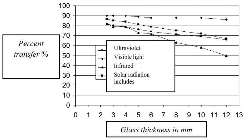
We can also demonstrate this important change in the table below. Increasing the thickness of the glass pane from 3.0 mm, which is the accepted thickness for windows of up to 1 sq.m. in homes, to a thickness of 12.0 mm as required in areas with windows of 7 sq.m. and more, table 14.2.2.2 (below) shows the change in percentage of transmitted radiation across the spectrum.
Table 14.2.2.2
Transfer of radiation through clear glass dependent on change of glass thickness from 3 mm to 12 mm
Spectral field | Change in transmitted radiation |
UV | Reduces by 24% |
Visible light | Reduces by only 5% |
Infrared | Reduces substantially by 64% |
Solar radiation, including all three spectra noted above | Reduces by 30% |
14.2.3 Spectral transmittance
Transmittance across the range of solar radiation, starting from 300 nanometers up to 2100 nanometers, through clear plate glass, is presented in figure 14.2.3.1 below:

Figure 14.2.3.1: Spectral transmittance through clear glass (according to 14.2.1.1)
The spectral transmittance through extremely clear glass is presented in figure 14.2.3.2 below, with data for Starphire glass by PPG
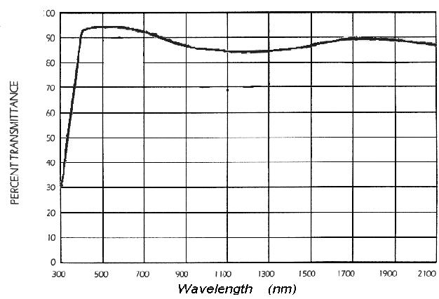
Figure 14.2.3.2: Spectral transmittance of extremely clear PPG Starphire glass (according to 14.2.1.2)
The extremely clear glass does admittedly let more visible light penetrate compared to regular glass, but it is worth noting that it also allows far more UV light through, which causes damage to materials within the building, and also far more infrared gets through, which represents much greater heat.
As is known, solar radiation reaching Earth contains almost no wavelengths shorter than 300 nanometers. This radiation is blocked by the ozone layer. From the graph we see that regular glass does not transmit radiation below 300 nanometers, even if this radiation would be able to reach us. The glass does however transmit a good proportion of radiation in the ultraviolet range between 300 to 400 nanometers. The highest level of transmission is in the range of visible light. Regular glass also transmits a substantial quantity of the hot infrared radiation, up to wavelengths of over 2,000 nanometers.
The extremely transparent light is able to transmit radiation with wavelengths of less than 300 nanometers, but as was explained above, this radiation does not reach Earth, so that equates it with regular glass for this aspect. From table 14.2.2.1 we can see that this glass excels because it allows higher penetration of light, but it also allows in 13.0% more UV in wavelengths of 300 to 400 nanometers, only 3.0% more in the visible range, and 15% more infrared. The most important element, however, is the overall, impressive effect this glass offers.
Figure 14.2.3.3 presents the spectral transmittance of the high quality glass developed by PPG, as noted earlier [see 14.2.1.3]. This glass, known as Azurlite, has a pale bluish tone. We can see that this glass lets in a little less visible light, but it blocks a great deal more UV and infrared than regular glass.
Azurlite is understandably more expensive than regular glass.
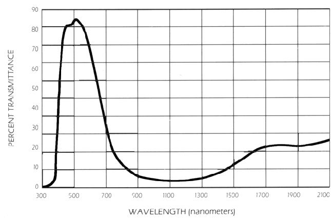
Figure 14.2.3.3: Spectral transmittance for PPG Azorlite glass [see 14.2.1.3]
14.3 Glass processing
Manufacturers of plate glass produce a wide range of types to cover diverse glazing needs and design requirements of construction technologies. Every manufacturer uses its own brand name as a way of presenting the product as unique, and provides catalogs with technical data. The data also presents transmittance of solar radiation, visible light, UV and infrared, returned light, mechanical characteristics, wear and tear, upholding of safety requirements, hues and finishes, as well as special requirements such as resistance to hostile atmospheres.
Below is an explanation of the main characteristics of different types of glass.
14.3.2 Pyrolysis glass
Pyrolysis is a chemical treatment under heat. Pyrolitic glass receives a coating or hue during the production process, with the glass reheated until softened. The coating is very stable, as is the entire sheet of glass.
Treating the glass with heat is also used to other advantages, such as increasing its strength and tempering, as explained below.
14.3.3 Heat strengthened glass
14.3.4 Tempered glass
This glass also undergoes reheating and higher pressure than heat strengthened glass. The cooling process is also a lot faster. The outcome is glass with much higher mechanical strength than heat strengthened glass, and up to 4 times stronger than annealed glass. The tempering process ensures that when the glass breaks resulting from pressure or mechanical shock, it shatters into small lumps which, not being sharp, means there is very little danger involved.
Tempered glass is suited for installation in places where high safety levels are required.
14.3.5 Monolithic glass
Following the tempering process, no further alterations can be made to the plate of glass. Therefore it must be cut to the appropriate size and given coatings and other treatments before tempering. During tempering meticulous attention is paid to uniform thickness. Monolithic glass is then delivered to the building site in its final form and size. No additional changes can be made to it.
14.3.6 Coatings
In addition to pyrolitic coating, which is usually part of the production process itself, it is currently common to employ additional advanced coating methods. After thoroughly cleaning and drying the glass, the plate is inserted into a sealed chamber from which the air is drawn out to create a vacuum. A metallic coating is sprayed onto the glass within a magnetic field in a process known as magnetic sputter vacuum deposition or MSVD. This allows for fine, uniform layers of coating to the glass. When several layers are wanted, the process is termed MLMSVD – multi layer magnetic sputter vacuum deposition.
14.4 Types of glass
The processes described above are the basis for production of many types of glass suited to diverse conditions such as climate, or architectonic, mechanical and safety requirements. Several additional types of glass are described below.
14.4.1 Laminated glass
Laminated ‘sandwich layers’ glass is described in section 10.4. This glass is made of two layers of relatively thin glass, glued to a film of plastic material such as polyvinyl butyrate, of a thickness of 0.8 mm (0.03”) as shown in figure 10.5.1. The thickness of the glass layers is determined according to the required mechanical strength, with the film glued between the two layers.
The thickness of the plastic film is between 0.5 to 2 mm, based on the requirements. The plastic film can be transparent or have additional characteristics such as UV radiation blocking or a tint. As noted above, laminated glass offers better acoustic insulation than a single pane of regular glass of the same total thickness.
The internal layer of laminated glass is always transparent. The required transmittance characteristics can be reached through the plastic film as described above, or by choosing an external glass with the necessary transmittance characteristics and tint. It is also possible to create combinations, for example an external tinted layer with UV blocking film, or any other combinations.
14.4.2 Selective glass
Clear glass transmits visible light (400 to 700 nanometers) and infrared, which is near the range of visible light (700 to 1,500 nanometers) at more or less equal rates, as shown in figure 14.2.3.1. Only a small amount of sunlight reaching Earth is in wavelengths of over 1500 nanometers.
Improving the function of thermal glass, which means preserving transmittance of as much visible light as possible while simultaneously reducing infrared light, manufacturers developed additives or coating for glass with selective transmittance abilities. The commercial brand names indicate the typical characteristics which help market the glass, such as: heat absorbing glass, heat resistant glass, and so on.
It is important to keep in mind that all glass absorbs a certain amount of radiation passing through it, causing the temperature of the glass to rise. The lower the transmittance quotient, the more heat will be absorbed and the glass will become hotter. The heat disperses, including into the air of the space inside as well as the air outside, in inverse proportion to the internal and external temperatures. What this basically means is that more heat is expelled into the cooler internal space in summer than into the external space, and in winter, more heat will be expelled to the outside since it is warmer inside.
A good example of selective glass is Azurlite, already mentioned above. Its spectral transmittance is presented in figure 14.2.3.2. The graph shows how the glass transmits visible light well, but substantially blocks both infrared and near-infrared.
The ratio between visible and near-infrared light is different from one type of glass to another, and from one manufacturer to another. Each manufacturer’s catalog provides the data for its glass.
Selective glass is produced in a wide range of colors: gray, light blue, blue, green, bronze-gold, brown and more. The color is usually chosen based on esthetic style considerations. However, choosing the right kind of glass should still rely on thoroughly examining the photometric qualities presented in the manufacturer’s catalog.
14.4.3 Reflective glass
Architects commonly use reflective glass, which add a dimension of prestige to a building. The additives and coatings described above alter transmittance of various light spectra. Another way to reduce the quantity of light transmittance through glass is to add an externally applied reflective coating. The thermal advantage is that part of the solar radiation hitting the glass is returned even before penetrate the plate of glass and warming it.
Reflective coatings can be applied in two ways. The most effective is penetration of metal oxides into one of the glass plates during the thermal pyrolitic processing immediately after production of the glass. This process ensures the coating’s stability over time despite cleaning, wind and dust abrasion, scratching, heating and so on. Usually the reflective coating is applied to the outward facing side. The second method is described below.
In addition to reducing the quantity of radiation penetrating the windows, reflective glass also prevents looking through the glass from the outside in during daylight hours. By contrast, people inside the building can see out. This undoubtedly provides a greater sense of privacy to those inside buildings with glass curtain walls. It should be noted, however, that the inverse occurs at night, when the reflective glass prevents people in the more strongly lit internal space from seeing outside, but allows outsiders in the darker space to see in, leaving those indoors with no privacy at all.
Occasionally a request is made to add the coating to existing clear glass windows. In such cases, a reflective film can be attached, such as that made by the American mega company 3M, or the windows can be coated by painting on a selective screen produced by SunX. Both methods require skillful application. The lifespan of the film or paint is limited, the coating can scratch during insufficiently careful cleaning, and over time this layer peels away from the glass.
The amount of reflectivity is determined by the mirror’s thickness. Visible reflectance needs to be carefully checked, as well as total solar reflectance. Usually, the values for both are very similar. As is known, clear glass returns 6% to 8% of the radiation reaching it. Reflective coating can increase those values to 35%, if not 40%. In addition to silvered mirroring, a tint can also be added to the glass, as noted above, to produce colored reflective glass.
Highly reflective glass should be used with caution due to the disturbances it can create. Returned solar radiation onto adjacent buildings can disrupt those buildings’ energy balance. Figure 14.4.3.1 presents a situation where a new building was constructed to the north of, and parallel to, an existing building with high reflective glass. the existing building’s northern facade receives solar radiation at different times of the day during the four seasons from an unexpected source: the southern facade of the new building. The temperature in rooms receiving this reflection rose noticeably, and even air conditioning was unable to dissipate the added thermal load.

Figure 14.4.3.1: Return of solar radiation from the southern wall of one building to the northern wall of the adjacent building. Diamond Exchange Center, Tel Aviv
A further danger is glare by light returned from reflective glass. Glare can disturb people working in nearby buildings. The reflection can become a serious danger when directed towards a main traffic route, causing drivers to become momentarily blinded by strong light appearing suddenly from unexpected directions, with the danger of accidents.
Reducing these disturbances to a bearable level requires that governments pass standards prohibiting the use of glass with greater than 20% reflectivity on other buildings or traffic avenues.
14.5 Determining glass thickness
The thickness of glass needed for windows is determined by the size together with additional considerations, but especially the static load of wind (in units of nanometers per sq.m.), a mechanical blow, and safety. ISO 1099 of 1981 [14.5.1] with its amendment standard of 1983 [14.5.2] set the minimum thickness of glass for window panes. Currently a new, updated version of the standards is under preparation.
In addition to the considerations noted above, price of the glass and its weight are also important factors when making choices. Obviously, the thicker the glass, the more costly it becomes. Its weight also increases, which must be taken into account when making statistical construction calculations.
In table 14.5.1 based on 1981 standards, the necessary thickness for window panes is determined by its surface area and the floor of the building:
Table 14.5.1: Determining thickness of glass for windows
Window area (sq.m.) | 0.5 1.0 1.5 2.0 2.5 3.0 3.5 4.0 4.5 5.0 | |
Window thickness (mm) | Up to 6 floors | 3.0 3.0 4.0 4.0 5.0 5.0 5.5 5.5 6.5 6.5 |
More than 6 floors | 3.0 4.0 4.0 4.0 6.5 7.0 7.0 8.0 8.0 8.0 | |
Note: as mentioned, the Israeli standards are currently being revised and data in the table above may need to be adjusted.
14.5.1 Buildings with standard risk
The thickness of glass in buildings with standard risk is set according to table 1 of the existing Revised Israel Strandards [14.5.2]. The maximum thickness is set by the static load weighed in newtons per sq.m. The weighted load calculation uses a formula with 3 coefficients. The first coefficient is set according to different areas of the country. The second takes into account the height above sea level, and whether the building site is open or concealed behind wind breakers or adjacent buildings. The third coefficient takes into account any irregularities of location such as hilltops, ravines, or particularly protected areas.
14.5.2 Buildings in danger areas
When requirements are made relative to high level safety for any reason, and in dangerous areas, the thickness of the glass must be increased and the glass installed must contain characteristics that reduce the risk of damage when the glass breaks. Security experts taking into account the purpose of the glass allow the following types:
Strengthened glass – poured onto a metal network
Tempered glass – as described earlier
Laminated glass – ‘sandwich’ glass, as described earlier
The minimum thickness for glass in areas of danger is presented in additional table contained in the Israel Standards.
14.6 Multilayered glazing
Looking at table 9.4.1 in chapter 9, we find that a window does admittedly provide a physical separation between the building’s interior and the outdoors, and ensures excellent penetration of daylight. However, its level of thermal insulation is very low. From this same table we also see that the thickness of clear glass has very little influence on the coefficient of thermal conductivity, the U-value, in Israel’s climate. In glass 3.0 mm thick this coefficient reaches 7.04 watts per sq.m. of glass panel to one degree Celsius of a different between inside and out. accordingly, the thermal conductivity coefficient for glass of 12.0 mm thickness would be 6.62 watts / sq.m. per Celsius degree. This means that increasing the thickness of the glass four-fold brings about a reduction of just 6% in the window’s thermal conductivity.
If we assume that inside the building a comfortable 20ºC is assured, and in a heat wave the temperature outside is 40ºC, the difference is 20ºC. If the windows or curtain walls of the building are installed with insulated 6.0 mm thick glass, the thermal conductivity coefficient will be 6.91 W/m2 ºC. Under such conditions, every sq.m. of window will transmit heat at the rate of 138 watts. This means that hourly, 7.0 sq.m. of glassed area lets 1.0 kilowatt of heat penetrate from outside to the interior. This heat is in addition to the radiation already penetrating the windows.
In winter, the flow of heat will reverse, from inside to out, which increases the costs of heating the internal space. If we assume a cold day or night, when the outside temperature is close to 0ºC, the different between internal and external temperatures is 20ºC, and the loss in heat conductivity transmittance through the glass will equate to the added heat penetrating during a heat wave. The single glass pane’s thermal functioning can be improved by installing selective glass or laminated glass, as described earlier. This is till only a partial improvement and insufficient for areas with harsh climates. In extremely cold areas, where the difference between internal and external temperatures can reach as much as 30ºC to 40ºC, this is insufficient. In our climate, it is worth examining whether major energy savings can be made by installing double glazing in very hot areas.
14.6.1 Double glazing
Significant improvements to thermal functioning can be reached by installing multilayered glass. Usually double layered glass, commonly known as double glazing, is the choice, as shown in figure 14.6.1.1. When the climate is particularly severe, or excellent thermal insulation is sought, triple layered glass is installed. The layers of glass have distances of between 5 mm to 15 mm between them. In the USA, the accepted distance is a half inch, or 12.5 mm.
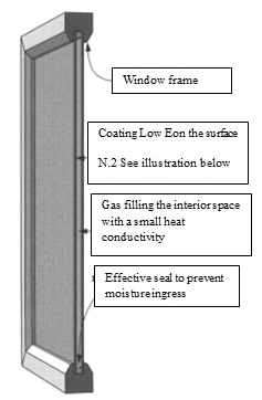
Figure 14.6.1.1: Window with double layer of glass
The double layer of glass is installed in a relatively large area, therefore its thickness is at least 4 mm and up to 6 mm. In even larger windows the thickness would reach between 8 to 12 mm, based on the window’s size. The total thickness of windows in this case can reach between 12 to 36 mm. The surface areas are numbered, as shown in figure 14.6.1.2, to allow indicating which coatings are intended for which side of each layer. The external surface of the external layer is numbered 1, and its inner face is 2. The externally facing surface of the next layer is number 3, and the internally facing side is 4.
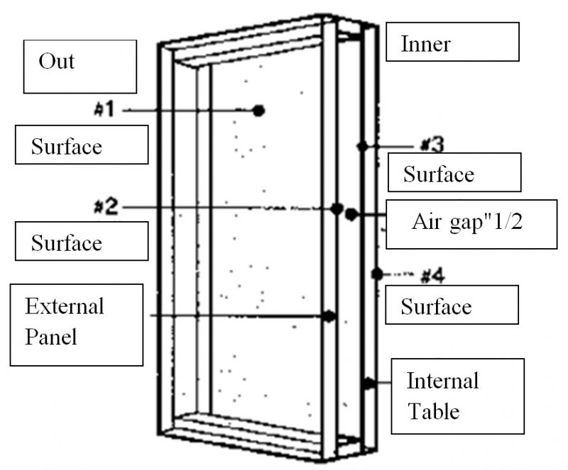
Figure 14.6.1.2: Numbering double layered glass
14.6.2 Structure of the layers
The internal plate of glass in double glazing is usually clear. The thickness of the internal plate can be less than that of the external plate. In windows needing 6.0 mm, for example, and to save on costs, the internal plate may be 4.0 mm. It is also common practice to install an internal layer of tempered glass to avoid mechanical damage from inside the space.
Usually the external plate’s inner side (surface area 2) receives the various coatings. Reflective coating is applied to surface 1. Often, more than one type of coating is used.
14.6.3 The window frame
The thermal role of the window frame is discussed in chapter 9, section 9.4.2. The transition from traditional wooden frames to metal frames, and especially aluminum, caused increased losses due to metal’s good heat conductivity. This in turn led to the development of frames with a thermal separation between the external and internal frame sections with a material of low thermal conductivity, as shown in figure 9.4.2.2 and accompanying data in table 9.4.2. In Israel, frames without thermal separation are usually installed, although many window makers offer more effective frames with separation for a higher price.
14.6.4 The space between the glass panes
The space between the layers of glass needs to be at a regular atmospheric pressure. This topic was also covered in chapter 9, section 9.4.3. As explained there, gas is needed in the space between the plates of glass to balance the pressure between inside and out. The gas must be dry, without water vapor. Usually dry clean air is sufficient but the heat conductivity can be reduced even further by using noble gases such as argon and krypton, or a mix of gases as shown in table 9.4.3.
14.7 Low emissivity glass
A revolutionary improvement in thermal functioning of windows was achieved with a coating known as low emissivity coating.
14.7.1 Emissivity
Every object having a temperature greater than that of its surroundings, which is usually air, emits thermal radiation in the infrared range relative to the temperature disparity. However, this also depends on the emissivity (or, emittance) of the surface. A kettle, for example, coating with shiny nickel will emit less radiation into the air around it than a non-shiny kettle.
Emissivity or emittance is indicated by the symbol ε, defined as the relative rate of thermal radiation emittance of a specific surface compared to the emittance by a black object at the same temperature. Therefore, the maximum value of ε can reach ε = 1. The less radiation emittance a surface has, the smaller its ε value will be.
Emissivity of different surfaces also depends on direction relative to the surface’s plane. Therefore, the average emission for all possible directions from the same surface is defined: that is, all directions that can indicate a hemisphere. This is known as hemispherical emissivity: from now on, when emissivity is referred to, it means hemispherical emissivity of thermal radiation. If you wish to delve further into the physics of heat transference in general, and emittance characteristics of different materials and surfaces, look for appropriate literature, such as in section [14.4.7.1].
14.7.2 Transmittance of radiation through glass
The transfer of solar radiation through glass depends on two main factors: the transmittance coefficient of the particular glass for the overall spectrum of sunlight, and the glass plate’s emissivity characteristics. Data on transmittance coefficients for several types of single layer glass are found in table 14.2.2.1. Additional data can be found in manufacturer’s catalogs.
Emissivity of glass surfaces of different hues as noted in table 14.7.2.1 is 0.840, that is, 84% of the theoretical emissivity of a black object. Reducing this transmittance of radiation via glass requires reducing its emissivity. This can be attained with a selective coating which penetrates radiation of the desired spectrum, which in our case is visible light, while reducing the transmittance of the undesired spectrum as far as possible, which in our case is heat radiation, or the infrared spectrum. This coating is known as low emissivity coating. Their sensitivity to moisture in the air means they cannot be used on single layer glass, but can be installed only in a sealed space, such as that between double glazing.
Reduction of radiation emission from lass depends on the surface to which the coating is attached. In hot climates, when the amount of heat penetrating into a building needs to be reduced, surface area 2 needs to be coated: this is the internal surface of the external pane, as shown in figure 14.7.2.1 In cold climates, when the goal is to prevent escape of heat inside the building to the outside, surface 3 should be coated, being the outward facing surface of the internal glass panel, as shown in the same diagram. If it is necessary to reduce radiation emission in both directions, then a Low E coating must be ordered, covering surfaces 2 and 3. This glass will be more expensive than coating on just one surface area.
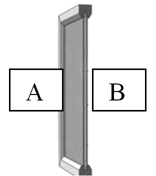
Figure 14.7.2.1: The surface requiring Low E coating
A – surface 2, for hot climates .
B – surface 3, for cold climates.
A further solution for reducing transmission of radiation in two directions is provided by the Mirror Heat company in USA. Their coating is applied on two sides of a very strong plastic film made of Mylar. The film is then stretched within the window frame in the middle of the space between the two planes of double glazing, as shown in figure 14.7.2.2. Coating the film is cheaper than coating the actual glass, but assembling the window is more complex and therefore more expensive.

Figure 14.7.2.2: Glazing with a two directional Low E film positioned between two planes of glass
In table 14.7.2.1 emissivity values are shown for several types of glass; to make the comparison feasible, all values are for glass of 6.0 mm thickness, as shown in chapter 9.6 above. The table indicates that the tint of glass has no influence on its emissivity. This means that emissivity for different colors of glass is the same. However, a shiny reflective coating, which is actually a mirror coating, reduces emissivity, as with the kettle mentioned earlier. The significant difference occurs due to use of Low E coating.
Low E applied to surface 2 of double glazing reduces radiation emissivity from the outside to the inside. It is therefore very suited to buildings in hot climates. Low E on surface 3 reduces emissivity from the inside to the outside, and is therefore well suited to cold climates.
14.7.3 Methods for installing the low emittance layer
So far, Low E has consistently been referred to as a coating. For the sake of precision, it is worth explaining the several methods for producing this layer.
Pyrolitic coating
Pyrolitic processing of glass has already been noted, where a coating material is sprayed onto the still hot, soft glass. The spray is absorbed into the glass, making it more resilient. Low E pyolitic coating allows a fine Low E layer, but it has insufficient emissivity. The outcome is a product with a shading coefficient of between 0.50 to 0.60, or a medium level only which does not ensure quality thermal insulation. A satisfactory thermal insulation requires shading coefficient below 0.50. In other words, a more efficient Low E layer is needed.
Low E film fastened to glass
A layer of film with low emittance can be produced using the MSVD (magnetic sputter vacuum deposition) method on a plastic mechanically strong film that withstands radiation, usually Mylar or a similar material. In the MSVD method, an entire roll of transparent film is inserted into a vacuum chamber. Once the air has been emptied out, a continuous process rolls the film while spraying it in a magnetic field. In fact, this process is very complex and requires spraying of a large number of layers, one after the other. Once this is complete, the film with its Low E layer is taken to the cutting hall where glass is cut to size, and film is fastened to it. Then the glass with the attached film is connected and joined to the frame used for double layer glazing. Care must be taken to ensure that the film will be on surface 2 or 3, to ensure it is on an internally facing pane of glass.
Low E film midway in the space
In section 14.7.2 we noted a glass production method with low emissivity through a film midway in the air space between the two panes of double glazing. This film can be produced with coating on both sides, giving the window very low emissivity in both directions, which ensures an extremely high level of thermal insulation. However, that actually turns the glazing into three layers. The cost of producing this kind of glazing is much higher, making it quite a bit more expensive than the more standard two layers of Low E coating.
Table 14.7.2.1: Coefficients for transmittance, return and emissivity for different types of glass
Thickness: 6.0 mm unless stated otherwise.
Indicators: : External layer of glass: 1 – outer surface; 2 – inner facing surface
Internal layer of glass: 3 – outer facing surface; 4 – inner surface
Type of glass or Trade name | Total solar radiation | Visible light | ||||||
או סימון החצרן | Transmittance | Return | Transmittance | Return | Emissivity | |||
% | % | % | % | % | % | |||
Surface Number | 1 | 2 | 1 | 2 | 1 | 2 או 3 | ||
Clear | 77.5 | 7.1 | 7.1 | 88.0 | 8.0 | 8.0 | 0.840 | 0.840 |
Bronze | 48.2 | 5.4 | 5.4 | 53.0 | 5.7 | 5.7 | 0.840 | 0.840 |
Gray | 45.5 | 5.3 | 5.3 | 43.0 | 5.2 | 5.2 | 0.840 | 0.840 |
Green | 48.7 | 5.6 | 5.6 | 74.9 | 7.0 | 7.0 | 0.840 | 0.840 |
Blue | 48.0 | 5.0 | 5.0 | 57.0 | 6.0 | 6.0 | 0.840 | 0.840 |
PPG – Starphire | 87.0 | 7.7 | 7.7 | 91.0 | 8.2 | 8.2 | 0.840 | 0.836 |
PPG – Azurlite | 37.0 | 6.0 | 6.0 | 72.0 | 5.0 | 5.0 | 0.838 | 0839 |
Clear reflective | 15.9 | 22.0 | 37.0 | 20.0 | 25.0 | 32.0 | 0.840 | 0.570 |
LowE clear | 60.0 | 17.0 | 22.0 | 84.0 | 5.5 | 7.8 | 0.840 | 0.100 |
LowE tinted עם גוון | 36.0 | 9.3 | 20.0 | 50.0 | 3.5 | 5.4 | 0.840 | 0.100 |
PPG LowE Sungate100 Clear שקופה | 29.6 | 23.0 | 6.0 | 68.0 | 4.0 | 6.2 | 0.838 | 0.086 |
PPG LowE Sungate50 Reflective | 40.0 | 27.3 | 21.4 | 54.0 | 6.0 | 12.0 | 0.839 | 0.086 |
Viracon LowE VE185 Clear | 56.4 | 14.4 | 23.7 | 85.0 | 5.4 | 5.2 | 0.840 | 0.090 |
Viracon LowE VE240 Dark gray אפורה כהה | 15.9 | 8.5 | 23.4 | 35.0 | 10.1 | 14.1 | 0.840 | 0.110 |
Laminated glass 3.00 + clear film 3.00 | 70.0 | |||||||
Clear acrylic 6.0 mm | 85.0 | |||||||
Clear fiberglass 2.0 mm | 60.0 | |||||||
14.8 Electrochromatic glass
14.8.1 Chromaticity
Chromaticity is the characteristic of a light transmitting material that alters transparency: in other words, the transmittance coefficient as impacted by radiation or an electrical field [14.8.1.1], [14.8.1.2], [14.8.1.3], [14.8.1.4].
14.8.2 Photochromaticity
The transparency of lenses used in spectacles can be changed by using something known as photochromatic glass. It becomes darker in strong light: that is, its light transmittance coefficient drops, as shown in figure 14.8.2.1. The glass lightens – that is, its transmittance coefficient rises – when the force of the light hitting the lenses decreases. This reaction is the result of changes in the position of molecules comprising the glass under the influence of light radiation. Radiation in other ranges of the spectrum, specifically UV and infrared, barely influence transparency. This change in position of the glass molecules does not impact other characteristics, such as strength and shape of the glass lends. The process is reversible and therefore no additional energy is required to activate it in either direction.
After the glass, such as the one described above for use in spectacles, has been produced, we hve no control over the rate of change in its transparency, which is dictated entirely by the strength of the light. There is no way to maintain its standard transparency in strong light.
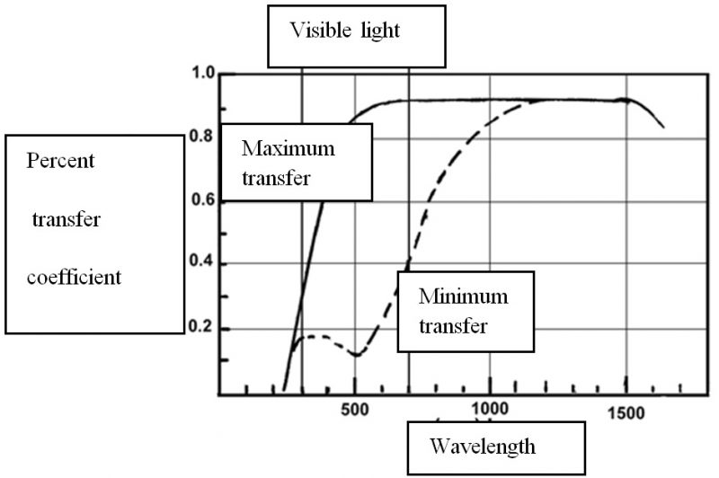
Figure 14.8.2.1: Typical spectral reaction of photochromatic glass
14.8.3 Thermochromatic glass
As with photochromaticity, a different composition of additives can be used to create glass where the change in transparency is caused by heat, or specifically, radiation of infrared from the sun or any other heat source. This is known as thermochromatic glass, which responds primarily to the infrared spectrum, as shown in figure 14.8.2.2 (see source in 14.8.2.1). In thermochromatic glass, the change in transparency is totally dependent on the strength of the radiation. We have no way of controlling transparency: we cannot make it stay clear in a state of exposure to strong radiation.
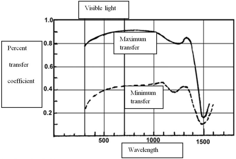
Figure 14.8.2.1: Typical spectral reaction of photochromatic glass
14.8.4 Electrochromaticity
As explained above, the photochromatic and thermochromatic changes are unequivocally produced in the production process. Thereafter, changes in transitions of radiation in the visible range, or infrared range, are determined wholly by the strength of the light hitting the glass.
Achieving effective window shading through chromatic means, we need to have better control of the rate of change of transparency. For this reason, a type of glass was developed having chromaticity adaptable through an electric current, and known as electrochromatic glass. It is comprised of two layers of regular glass, with several layers installed between them that allow regulating the rate of transparency by an electric current that is managed by the control system set by parameters of our choosing.
14.8.5 The structure of the electrochromatic layer
The layer of electrochromatic coating between the outer layers of glass comprises 5 intermediary layers, coated one after the other, as shown in figure 14.8.5.1. The electrochromatic layer operates like an electric cable. The two outer, clear layers serve as contacts: electricity-conducting electrodes. When connected to a source of direct current, such as an electric battery, a positive electric charge is created, and in the other, a negative electric charge, relative to the electric voltage between the electrodes. The three electrochromatic layers are isolated from the electrodes and there is no flow of current between them. Tis condition creates an electric field between the clear electrodes, as in any cable. The electric field causes the exchange of ions between the electrochromatic layers. As a result, the transparency alters: that is, the amount of transmittance of radiation through the glass alters.
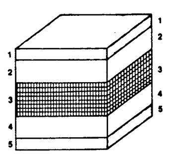
Figure 14.8.5.1: Layers of electrochromatic coating Structure of the coating:
1 – Clear electricity conductor
2 – Counter electrode
3 – Ion exchanging conductor
4 – Electrochromatic film
5 – Clear electricity conductor
14.8.6 Characteristics of the electrochromatic coating
Electrochromatic glazing is currently in advanced stages of development, but has not yet reached expansive use. It is used for specific purposes, such as the pilot’s cockpit window in newest jets. This glass is still very expensive for general use, but expectations of it are great, and it is already being given very suitable names, such as “The Smart Window.” Forecasts for mass production and acceptable prices are optimistic, and manufacturers of the coating and the glass are putting up tough competition to be the first with a reliable, mass market product.
Without a doubt, when this glass becomes readily available, another revolution in glazing will come about. Electrochromatic glass will be the first to enable dynamic control of the transparent element of a building’s cladding.
Once this glass reaches the general market, it will be possible to obtain with a range of characteristics to suit diverse needs. At the current stage, the table below presents several of the electrochromatic coating’s currently known characteristics.
Table 14.8.5.1: Characteristics of electrochromatic glass
Light – maximum transparency | Dark minimum transparency | |
Transmittance of overall solar radiation – TS 50% – 70% | 50% – 70% | 10% – 20% |
Light transmittance – Tv | 50% – 70% | 10% – 20% |
Infrared radiation return – Rnir | 10% – 20% | > 70% |
Activation voltage | 1 – 5 volt | |
Memory | 1 – 24 hours | |
Full changeover speed | 1 – 60 hours | |
Repeat actions over the layer’s life span | Up to 1 million | |
Life span | 5 – 20 years | |
Regular activation temperature 70º | C 300 – C 700 |
14.8.7 Forecast energy savings
Studying the known characteristics of electrochromatic glass indicates that a potential saving in energy can be expected once the technology reaches mass production. Forecasts were, and remain, optimistic, but development is still in progress and neither a target date for mass production nor final costs are known.
The expected saving from electrochromatic glass derives from the possibility of dynamic, planned control which on one hand constantly takes into account solar and sky radiation while simultaneously configuring the requirement of light and heat within the space. This will allow optimization of energy supply for cooling, and optimally balancing natural light or electrical alternatives. Figure 14.8.7.1 offers a schematic explanation of the balance between electrical energy for light compared to energy for cooling, per sq.m. of internal space.
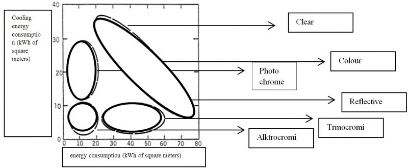
Figure 14.8.7.1: Electrical energy requirements (kWh) per sq.m. for lighting and cooling of internal space as a function of type of glass
From the diagram above, we see that the currently accepted types of window glass (clear, selective with tint, and reflective) cause high electrical energy consumption. Regular clear glass allows much higher penetration of natural light and is therefore cost saving on energy for lighting, but it also causes higher consumption of energy for cooling. The various types of tinted glass have lower transparency compared to standard clear plate glass. They allow lower cooling energy consumption, but cause an increase in lighting energy consumption. Reflective glass considerably reduces cooling energy consumption, but due to its low level transparency, only a very small percentage of natural light can penetrate, causing an increase in lighting energy needs.
As can easily be seen from the diagram, various types of electrochromatic glass (photochromatic, thermochromatic, electrochromatic) allow significant energy savings. However, the dynamic activation of electrochromatic glass will hold the highest potential for energy savings in buildings.
We definitely look forward to mass production and application of electrochromatic glass in the near future.
14.9 Architectonic glass
Several of the largest glass manufacturers produce glass with coatings having geometric designs, as shown in figure 14.9.1. The PPG company labeled them Patternlite Glass. The coating is made of extremely finely ground boro-silicate glass. Inorganic pigments of the desired color are added to produce a substance called Ceramic Frit. This frit is sprayed over the entire glass plate through shaped netting. The glass is then heated to 620º C (1150º F), turning the ceramic coating into an integral part of the glass.
The range of colors includes black, gray, brown, blue, green and peach.
Figure 14.9.1 shows three basic shapes. Other shape combinations can be ordered specially. The advantage of this glass is that it does not conceal what can be seen from the inside, yet reduces the amount of penetrating light into the structure, thereby reducing the thermal load during hot seasons, and the amount of glare throughout the year.
The main disadvantage of architectonic glass is its high cost. It is produced in relatively small quantities, which increases production costs.

Figure 14.9.1: Architectonic glass – different types of geometric coatings
14.10 Concealing glass
Concealing glass, or as it is more commonly known, Spandrel Glass, is impervious to radiation transmittance but preserves its appearance like regular plate glass of the same hue. This glass serves to conceal and block part of the building’s facade while maintaining a uniform appearance with the rest of the glass curtain wall. It is produced in the same way as architectonic glass.
This glass might be installed in the area beneath the viewing windows and down to the floor. In this section of concealed glass it is possible to install supply pipes and channels and many other building details that are not seen from the outside.
14.11 Glass block
Glass blocks, also known as glass bricks, are made of double layered glass in sizes from 100 x 100 mm with a thickness of between 50 to 100 mm. The blocks, as shown in figure 14.11.1, are usually made from clear glass, but transmit scattered light, concealing whatever is on either side of them. They are used to good advantage as a decorative element in homes, public buildings, industrial structures, sports centers, stairwells and more.
As can easily be seen from the diagram, various types of electrochromatic glass (photochromatic, thermochromatic, electrochromatic) allow significant energy savings. However, the dynamic activation of electrochromatic glass will hold the highest potential for energy savings in buildings.
We definitely look forward to mass production and application of electrochromatic glass in the near future.
14.12 Manufacturers of glass
Pilkington, of England, has already been mentioned, as well as PPG – Pittsburgh Plate Glass in USA. Several more manufacturers of renown include Saint Gobain of France [see 14.11.1], Glaverbel of Belgium, LOF – Libby Owens Ford of USA, and Viracon, also in the USA.
Phoenicia Glass in Haifa Bay, Israel, used to produce glass for windows. The company is currently located in the Tzippori Industrial Center and markets diverse glass products, including laminated glass of varying thicknesses and tints.
Many other glass companies purchase their glass from large manufacturers and add finishes or coating in a range of colors, selling the final product under trade names to window makers and construction companies. One such is Heat Mirror of the USA, which produces glass with excellent Low E coatings. Ipasol from Germany is another quality company.
References for chapter 14:
[14.2.1.1] PPG, 1996, Performance Data for Clear Float Glass C-1, Pittsburgh Plate Glass Industries, Pittsburgh.
[14.2.1.2] PPG, 1996, Performance Data for Starphire Float Glass ST-1a, Pittsburgh Plate Glass Industries, Pittsburgh.
[14.2.1.3] PPG, 1996, Performance Data for Azurlite Float Glass AL-1a, Pittsburgh Plate Glass Industries, Pittsburgh.
[14.5.1] Israel Standards ISO 1099, October 1981.
[14.5.2] Israel Standards ISO 1099 – Adjustment 1, Novemer 1983
[14.4.7.1] McCluney W. R., 1994, Introduction to Radiometry and photometry, Artech House, Boston, London.
[14.8.1.1] Lampert C. M., 1991, Large Area Chromogenics for Smart Windows, Energy and Environment Division, Lawrence Berkeley Laboratory, 1 Cyclotron Road, Berkeley, CA 94720
[14.8.1.2] Johnson T. E., 1991, Low-E Glazing Design Guide, Butterworth Architecture, Boston, London.
[14.8.1.3] Reilly S., Arasteh D., Selkowitz S., 1991, Thermal amd Optical Analysis of Switchable Window Glazings, Solar Energy Materials, pp. 1-14, Elsevier Science Publishers, North Holland.
[14.8.1.4] Yu P. C., Nazri G., Lampert C. M., 1986, Spectroscopic and Electrochemical Studies of Electrochromic Hydrated Nickel Oxide Films,SPIE 3rd International Conference on Optics and Electrooptics, Insbruck, Austria.
[14.11.1] Saint Gobain, 1997, Glass in Windows, Saint Gobain, Brussels, Belgium
