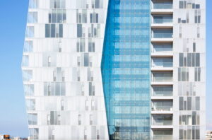
Is an especially elegant glass wall where the construction carrying the glass is of stainless steel cable stretched in a cross weave, creating a delicate, even exotic, appearance of a fine netting much like a spider’s web.
The first cable net wall of its kind was unveiled in 1992 at the Kempinski Hotel, Munich. The wall’s width is 40 meters, with a height of 25 meters. In this project, stainless steel warp and weft cables of 22 mm thickness were installed, with pretension allowing maximum bending at the wall’s center of 900 mm. Following the project’s success, additional similar projects were installed, the most notable being the New Poly Plaza in the Chinese city of Beijing.
The cable net wall system is, as noted, made of stainless steel cables stretched across the building’s structure in a warp and weft formation, where each joint of horizontal and vertical is installed with a stainless steel device that grips four corners of glass.
How does the cable net wall system work?
The fundamental condition for the system’s success is cable tension. To achieve good resistance to the bending resulting from the force of wind on the glass and which transmits to the cable construction, we must allow the existence of great forces of tension. Because these forces transmit to the building’s walls, the building must be able to bear them. therefore, the building must be planned in advance to bear the cables’ stress load. This is not a simple achievement: the smaller the amount of bending we wish to allow, the tighter the tension must be.
It’s easy to understand the difficulty, therefore, in planning a building able to bear the tension of the cables that in fact constitute the structure for the glass curtain wall. This led to examining the possibility of allowing irregular bending in the wall, because the cables do not carry bending moments that may cause a structural fracture. Nonetheless, large bending may cause a fracture in the glass and/or cause a sense of discomfort among those behind the cable wall.
The glass:
Since it is clear that large bending must be allowed in the wall, without which the cable tension will be too large for the building to absorb, it becomes necessary to use a flexible glass which can withstand the bending force on one hand, and the structural forces on the other, and which can be harnessed to the cables in a way that prevents development of irregular force. The recommended glass is of a kind that withstands 100 newtons / sq.m. Additionally, should a fracture occur, it is vital for all the parts of the glass to remain in their place. Therefore, the recommended glass is a safety glass of the laminated glass kind. It is also no less recommended to avoid the potential for thermal fracturing derived from the existence of nickel sulphide particles, and to treat the glass with a thermal process known as heat shock, which assists in locating such particles before the glass is installed, and allows avoiding using these panels of glass.
Vibrations:
The Cable Net Wall reaching heights may absorb winds of varying speeds along different areas. The cables, even if tense, will nonetheless behave like springs, with vibrations developing along the length of the wall. These can be restrained because the cables behave like a spring, but the vibrations may also be noisy and cause a sense of discomfort to people near the glass wall. When planning the wall, it is vital to ensure that expectable vibrations will not reach the resonance room, which may cause serious damage to the glass panels.
Glass harnessing devices:
In general, the positioning of glass harnessing devices will be at the junctions between the vertical and horizontal cables. At every junction, a device made of stainless steel is installed with its most outstanding feature being to prevent the development of irregular force in the glass. Every device clamps onto up to 4 glass panels, with the harnessing point being flexible and allowing changes to the position of the glass panel by up to 10º. In principle, it is highly recommended not to perform drilling near a cable net wall, since these areas are particularly sensitive.
A bit more about Cable Net Walls
1. Structural elongation
Since stainless steel cables are built of filaments interwoven into a strand, and several strands are interwoven to form the cable, there is space between the filaments and the strands. These spaces allow the existence of structural elongation, when we apply tensile loads to the cable. This elongation can reach up to 1% of the cable’s length: should the cable not be stretched to the final load, these spaces will remain and the elongation will exist any time force is increased. To avoid this phenomenon, pretensing should be implemented each time for maximum loa
2. Elastic elongation
Elastic elongation derives primarily from the material’s natural characteristic of changing shape when load is activated, and returning to its former status once the load is released. Stainless steel cables elongate under load and shrink with the load’s release. Even though elastic elongation is not linear relative to load, the elastic model offers the closest reasonable option, being 1.5 x 10⁵ Mpa.
Calculating cable tension:
For a cable harnessed between two points, and weighted (W) differently along its length (S), we can presume the formation of an arc with a radius (R) and bending (d) as follows:
We see that the forces transmitted to the anchor points are perpendicular to each other: the horizontal force (H) and vertical force (V). The weighting of these two forces is the tension (T).
This can be presented as follows:
If, by way of example, we assume that the force loaded on a cable 15 meters long is 200 kg per meter, and we allow for bending of 500 mm, what will the tension be?
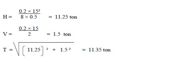
Conclusion:
1. V is negligible relative to H
2. The tension is high, and the building must be planned to carry this load.